

Skip to content

GPS distribution

GPS timing for equipment rooms that can’t see the sky.

GPS is the heartbeat of the network. Intelibs delivers a stable, accurate signal to equipment rooms the sky can’t reach.

Illustration of an Intelibs GPS over Fiber system: GPS antennas on the Intelibs Front End Unit on the roof receive the satellites, fiber carries the signal down to the equipment room, and the FDU and BEUs deliver timing to every carrier rack. Lenses show the FEU and the GPS rack enlarged. RACKS IN SYNC 4 / 4 GPS SATELLITES B1 · EQUIPMENT ROOM · NO SKY VIEW FIBER RISER BTS GPS OVER FIBER · FEU FEU · SHOWN ENLARGED FDU BEU BEU FDU + BEUs · ENLARGED

Use case: urban canyons.

Streets lined with tall buildings create canyon-like environments where reception is poor. Classic examples include Chicago’s Magnificent Mile, the Canyon of Heroes in Manhattan and Hong Kong’s Kowloon and Central districts.

Urban canyons affect local conditions, including radio reception and GPS signals. That matters because GPS is a key timing source for telecommunications, providing the global reference used to synchronize real-time systems such as cellular networks.

Use case: centralized carrier equipment.

Wireless carriers increasingly centralize radio equipment in one location and extend coverage over fiber. Every piece of RF source equipment in that room needs its own GPS feed, and as the heartbeat of the network, that timing source must be stable, accurate and highly available.

The Intelibs solution.

GPS over Fiber carries the GPS signal hundreds of feet into troublesome areas, giving equipment in urban canyons a strong, reliable signal. Our GPS over Fiber products feature the industry’s first NEBS Level 3 certification for telco-qualified equipment.

For central BTS locations, the Intelibs GPS distribution architecture scales from a single rack to multi-rack, multi-room configurations using Fiber Distribution Units (FDU).

Scales from one rack to many rooms.
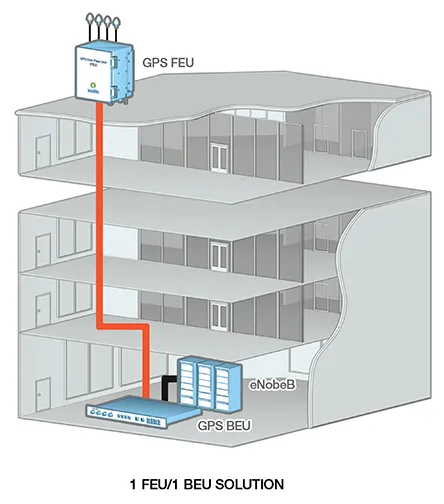
Diagram of a GPS over Fiber system from a rooftop antenna to equipment in the basement
One FEU on the roof feeding one BEU in the basement.
Animated diagram of an Intelibs GPS over Fiber system with one FEU, one FDU and multiple BEUs: the FDU splits the optical GPS signal to BEUs in several racks, and a BEU with four CDUs distributes it over coax to a rack of receivers RACKS IN SYNC 4 / 4 FEU FRONT END UNIT FDU FDU FIBER DISTRIBUTION UNIT BEU BEU + BTS BEU BEU + BTS BEU BEU + BTS BEU CDU CDU CDU CDU RECEIVERS BEU + 4 CDU FIBER COAX (GPS RF)
One FEU feeding multiple BEUs through an FDU, with coax distribution units.
Animated diagram of Intelibs GPS remote monitoring: at each site the FEU on the roof feeds the BEU beside the eNodeB, and every BEU reports over Ethernet and the internet to the NOC through web and SNMP interfaces, and to a web client NOC GPS SITES SITE 1 GPS LOCKED SITE 2 GPS LOCKED SITE 3 GPS LOCKED WEB CLIENT WEB INTERFACE SNMP INTERFACE WEB INTERFACE INTERNET SITE 1 SITE 2 SITE 3 FEU ON THE ROOF · BEU + eNodeB IN THE BASEMENT SITES REPORTING 3 / 3
Remote monitoring over a Web/SNMP-based portal.

Let’s talk about your building.

New construction, a renovation or a coverage problem today. An Intelibs RF engineer will help you find the right approach.

Preview of the new intelibs.com

What do you think of our new website?

We’re redesigning our site. Tell us what works and what we should improve. It takes a minute.

Overall, how do you rate the new design? *

We only use this to improve the website.